Cosori Dehydrator Manual: A Comprehensive Guide
Welcome! This guide provides detailed instructions for your Cosori dehydrator (Model CP267-FD)․ Explore recipes at recipescosori․com and contact support via email or toll-free number․
Understanding Your Cosori Dehydrator (Model CP267-FD)
Your Cosori CP267-FD food dehydrator is a versatile kitchen appliance designed for preserving food, creating healthy snacks, and exploring culinary creativity․ This model utilizes a gentle dehydration process, removing moisture from foods while retaining essential vitamins and minerals․ Unlike traditional methods, dehydration minimizes nutrient loss, offering a convenient way to enjoy seasonal produce year-round․
The dehydrator operates by circulating warm air around food placed on multiple trays, effectively reducing water content and inhibiting microbial growth․ This process extends shelf life naturally, without the need for artificial preservatives․ It’s ideal for fruits, vegetables, meats (for jerky), herbs, and even pet treats․
Understanding the core functionality – consistent temperature control and airflow – is key to successful dehydration․ The CP267-FD boasts a 48-hour timer and adjustable temperature settings, allowing for precise control over the drying process․ Familiarizing yourself with these features, alongside proper food preparation techniques, will unlock the full potential of your Cosori dehydrator․ Refer to recipescosori․com for inspiration and detailed guidance․
Key Features and Components

The Cosori CP267-FD boasts several key features designed for efficient and user-friendly operation․ A prominent feature is its adjustable thermostat, allowing temperature control for optimal dehydration of various foods․ The 48-hour timer provides flexibility, enabling unattended operation and precise drying times․
Component-wise, the dehydrator includes multiple stainless steel trays – crucial for even airflow and preventing food contamination․ These trays are dishwasher-safe, simplifying cleanup․ A top-mounted fan ensures consistent air circulation, vital for uniform dehydration across all trays․ The housing is constructed for durability and quiet operation․
Furthermore, the unit features a digital control panel for easy setting of temperature and time․ A rear vent facilitates moisture expulsion, enhancing dehydration efficiency․ The included user manual and access to recipescosori․com provide comprehensive guidance․ These combined elements make the CP267-FD a powerful and convenient tool for food preservation and snack creation․
Initial Setup and Preparation
Before your first use, unpack the Cosori CP267-FD dehydrator and remove all packaging materials․ Thoroughly wash the stainless steel trays, the fruit leather sheet, and the mesh screen with warm, soapy water․ These components are dishwasher safe for convenient cleaning, but handwashing is also acceptable․
Place the dehydrator on a stable, level surface with adequate ventilation around all sides․ Ensure the rear vent is unobstructed to allow for proper moisture expulsion during operation․ Familiarize yourself with the placement of the trays and how they slide into the unit․
It’s recommended to run the dehydrator empty for 30-60 minutes on a low temperature setting (around 135°F or 57°C) to eliminate any potential manufacturing odors․ This initial ‘burn-off’ period ensures a clean and odor-free dehydration experience․ Refer to the included manual for detailed instructions and safety precautions before proceeding․
Control Panel Overview & Functions
The Cosori CP267-FD features an intuitive digital control panel․ The Temperature Control buttons allow you to adjust the dehydration temperature between 95°F and 167°F (35°C – 75°C), crucial for different food types․ The Timer function enables precise dehydration times, ranging up to 48 hours, ensuring optimal results․
The Start/Pause button initiates or temporarily halts the dehydration process․ The Stop button completely ends the cycle․ A clear LED display shows the remaining time and selected temperature․ Some models include a Fast button for quicker temperature adjustments․
Understanding these functions is key to successful dehydration․ Experiment with different temperature and time combinations based on the food you’re processing; Always refer to the dehydrating times and temperatures guide within the manual for specific recommendations․ Proper use of the control panel guarantees consistent and delicious dehydrated foods․
Dehydrating Times and Temperatures: A General Guide
Successful dehydration relies on appropriate temperature and time settings․ Fruits generally require temperatures between 135°F (57°C) and 175°F (79°C) for 6-12 hours, depending on thickness and type․ Vegetables typically need 125°F (52°C) to 165°F (74°C) for 6-16 hours, with leafy greens dehydrating faster than root vegetables․
Meats, especially for jerky, demand a higher temperature – 160°F (71°C) to 170°F (77°C) – for 4-8 hours, prioritizing food safety․ Herbs dehydrate quickly at 95°F (35°C) to 115°F (46°C) in 2-4 hours․ Mushrooms benefit from 125°F (52°C) to 135°F (57°C) for 6-12 hours․
These are general guidelines; adjust based on desired texture and humidity․ Thicker pieces require longer times․ Regularly check food for dryness, aiming for a leathery or brittle consistency․ Always consult specific recipes for optimal results and prioritize food safety by ensuring thorough dehydration․
Preparing Food for Dehydration
Proper food preparation is crucial for optimal dehydration results and preservation․ Begin by washing all produce thoroughly to remove dirt and contaminants․ Peeling is often recommended for fruits and vegetables with thick skins, though some nutrients reside within the peel․ Slicing food into uniform pieces – approximately ¼ inch thick – ensures even drying․ Consistency is key!
For fruits, consider pretreatments like lemon juice dips to prevent browning․ Blanching vegetables briefly in boiling water deactivates enzymes that can affect flavor and color during storage․ Marinating meats enhances flavor and can aid in preservation․
Remove seeds and pits before dehydrating․ Arrange food in a single layer on the dehydrator trays, ensuring adequate air circulation․ Avoid overcrowding․ Pat food dry with paper towels to remove excess moisture before placing it on the trays․ This speeds up the dehydration process and improves results․

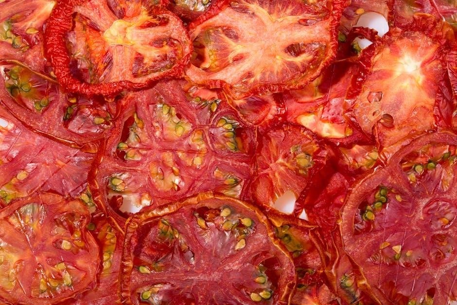
Dehydrating Fruits: Best Practices
Achieving perfectly dehydrated fruit requires attention to detail․ Generally, a temperature range of 135°F to 175°F (57°C to 79°C) is ideal, though specific times vary․ Apples and bananas typically take 6-12 hours, while berries require 8-16 hours․ Always check for flexibility – fruit should be leathery and not brittle․
Pretreatment is vital for preventing discoloration․ A lemon juice bath (1 tablespoon lemon juice to 1 cup water) works wonders․ For fruits prone to sticking, like mangoes, lightly coat trays with cooking spray․ Rotate trays midway through the drying process for even results․
Consider the fruit’s moisture content․ Pineapple and other juicy fruits may need longer dehydration times․ Properly dehydrated fruit should be pliable, slightly chewy, and free of any visible moisture․ Store in airtight containers in a cool, dark place for optimal shelf life․ Explore recipescosori․com for inspiration!

Dehydrating Vegetables: Techniques for Optimal Results
Dehydrating vegetables demands careful preparation for optimal flavor and texture․ A temperature range of 125°F to 175°F (52°C to 79°C) is generally recommended, adjusting based on the vegetable․ Root vegetables like carrots and beets require 8-12 hours, while leafy greens like kale may only need 6-8 hours․ Ensure even slicing – consistency is key!
Blanching is crucial for most vegetables․ Briefly submerge in boiling water (1-3 minutes) then immediately shock in ice water to stop the cooking process․ This preserves color, flavor, and nutrients․ Pat vegetables thoroughly dry before arranging on dehydrator trays, avoiding overcrowding for proper airflow․
Consider seasoning before dehydration․ A light sprinkle of salt or herbs enhances flavor․ Regularly check for dryness; vegetables should be brittle and snap easily․ Store dehydrated vegetables in airtight containers, protecting them from light and moisture․ Discover more tips at recipescosori․com!
Dehydrating Meats: Safety and Preparation
Dehydrating meats requires strict adherence to safety guidelines to prevent bacterial growth․ A consistent temperature of 160°F (71°C) is vital for eliminating harmful pathogens․ Lean cuts of meat are preferable, as fat can become rancid during storage․ Marinating meats beforehand not only enhances flavor but also helps tenderize them․
Pre-cooking is often recommended, especially for thicker cuts․ This reduces dehydration time and ensures thorough cooking․ Slice meat into ¼-inch thick strips, following the grain for easier chewing․ Arrange slices in a single layer on the dehydrator trays, ensuring adequate space between pieces․
Dehydration times vary depending on the meat and thickness, typically ranging from 4-12 hours․ Meat is properly dehydrated when it’s leathery and bends without breaking․ Cool completely before storing in airtight containers․ Refer to recipescosori․com for detailed recipes and safety information․
Making Jerky with Your Cosori Dehydrator
Creating delicious jerky with your Cosori dehydrator is a rewarding experience! Begin with lean cuts of beef, venison, or poultry․ Partially freezing the meat before slicing makes it easier to achieve uniform ¼-inch thick strips․ Marinades are key – experiment with flavors like teriyaki, peppered, or sweet and savory․
Marinate the meat for at least four hours, or preferably overnight, in the refrigerator․ This infuses flavor and tenderizes the protein․ Before dehydrating, pat the marinated meat dry to remove excess moisture․ Arrange the strips in a single layer on the dehydrator trays, avoiding overlap․
Set the temperature to 160°F (71°C) and dehydrate for 4-8 hours, checking for desired texture․ Jerky is done when it’s leathery and bends without breaking․ Cool completely and store in an airtight container․ Explore recipescosori․com for diverse jerky recipes and inspiration!
Dehydrating Herbs and Spices
Preserve the vibrant flavors of your garden by dehydrating herbs and spices with your Cosori dehydrator! This method concentrates their potency, creating intensely flavorful additions to your culinary creations․ Begin by thoroughly washing and drying fresh herbs – remove any damaged or discolored leaves․
For leafy herbs like basil, parsley, and mint, spread them in a single layer on the dehydrator trays․ For spices like chili peppers or ginger, slice them thinly for faster and more even drying․ Set the temperature to 95-115°F (35-46°C) and dehydrate for 2-4 hours, checking frequently․
Herbs are done when they crumble easily, and spices become brittle․ Once cooled, store dehydrated herbs and spices in airtight containers away from light and heat to maintain their flavor and aroma․ Discover unique spice blend ideas at recipescosori․com!
Using the Timer Function Effectively
The Cosori dehydrator’s timer function offers convenience and precision in your food preservation process․ Utilizing the timer ensures optimal dehydration without constant monitoring, allowing you to set it and forget it – within safe parameters, of course! The timer range extends up to 48 hours, accommodating various food types and desired levels of dryness․
To set the timer, press the “Time” button and use the “+” and “-” buttons to adjust the duration․ The display will show the remaining dehydration time․ Remember to consider the specific dehydrating times recommended for different foods (refer to the general guide)․
Once the timer reaches zero, the dehydrator will automatically shut off, preventing over-drying․ However, it’s always wise to check the food’s texture to confirm it’s reached your desired consistency․ For extended dehydration periods, periodically check and rotate trays for even results․ Explore recipescosori․com for suggested timings!
Cleaning and Maintenance
Regular cleaning is crucial for maintaining the performance and hygiene of your Cosori dehydrator․ Always unplug the unit before cleaning! The trays and dehydrating sheets are dishwasher safe, offering a convenient cleaning option․ For stubborn food residue, a warm, soapy water soak is recommended before washing․
The dehydrator base should be wiped down with a damp cloth․ Avoid immersing the base in water, as this could damage the electrical components․ A mild detergent can be used for tougher stains, but ensure it’s thoroughly rinsed and the base is completely dry before reassembling․
Inspect the fan intake and exhaust vents regularly to remove any dust or debris, ensuring proper airflow․ Proper maintenance extends the lifespan of your dehydrator and guarantees food safety․ Refer to recipescosori․com for additional tips and support resources․

Troubleshooting Common Issues
Dehydrator not turning on? First, ensure it’s properly plugged into a functioning outlet․ Check the power cord for any damage․ If the issue persists, contact Cosori support at (888) 402-1684 (M-F, 9am-5pm PST)․ Uneven dehydration? Rotate the trays midway through the drying process to promote consistent results․

Food sticking to trays? Use parchment paper or non-stick dehydrator sheets, readily available for purchase․ Timer not working correctly? Verify the timer is set accurately and hasn’t defaulted to a different setting․ A reset of the unit might resolve the issue․

Unusual noises? Ensure the dehydrator is placed on a level surface․ If noises continue, contact customer support․ For further assistance and FAQs, visit recipescosori․com․ Remember to always prioritize safety and consult the manual before attempting any repairs․
Safety Precautions and Warnings
Important Safety Instructions: Always unplug the Cosori dehydrator before cleaning or performing maintenance․ Never immerse the base containing the electrical components in water or any other liquid․ Ensure proper ventilation during operation; do not block air vents․ Keep the dehydrator away from flammable materials․

Hot Surfaces: The dehydrator’s interior surfaces become hot during use․ Exercise caution and use oven mitts when handling trays․ Allow the unit to cool completely before disassembling or cleaning․ Supervise children closely when the dehydrator is in operation․
Electrical Safety: Do not operate the dehydrator with a damaged cord or plug․ If the appliance malfunctions, discontinue use and contact Cosori support at (888) 402-1684․ For comprehensive safety guidelines and policies, refer to the full user manual and recipescosori․com․
Recipe Ideas and Resources (recipescosori․com)
Unlock Culinary Creativity: Expand your dehydration journey with a wealth of recipes and inspiration available at recipescosori․com! Discover innovative ways to preserve fruits, vegetables, meats, and herbs, tailored specifically for your Cosori dehydrator (Model CP267-FD)․ From savory jerky and wholesome fruit leather to flavorful spice blends and nutritious dog treats, the possibilities are endless․
Exclusive Content: The website features a dedicated recipe book designed to maximize your dehydrator’s potential․ Explore detailed instructions, ingredient lists, and helpful tips for achieving optimal results․ Find ideas for both beginner and experienced dehydrators, ensuring a delightful experience every time․
Community & Support: recipescosori․com also serves as a hub for connecting with fellow Cosori users․ Share your creations, exchange tips, and access additional support resources․ Don’t forget to check for new recipes added regularly!